Originally I wanted to call this blog “How to make a Dactyl Manuform keyboard for 100$ or less” but it seemed too clickbaity so I changed the title. I wanted to give it that name because building a custom keyboard can be really expensive and I wanted to make it as cheap as I could.
The main reason why I wanted it to be really cheap is because I never made a keyboard before and this was my first time. I thought that I would mess it up or break something so I wanted to use the cheapest parts that I could find until I learn how to do it properly and then make a build with good quality parts. Little did I know that it’s hard to mess something up to the degree that it’s not fixable. 90% of the work is basically soldering stuff together and if you solder something wrong, it’s easy to desolder it and try again. Unless you break or melt something, it should be fixable. If you go to the Full list of parts section, you will see that the total amount for all parts was 80.96 USD (without the tools like soldering iron or glue gun). I checked the prices for tools on AliExpress and it’s even possible to add the cheapest tools and still be under 100 USD.
Living in a country where Amazon delivery is still a myth, I had to use AliExpress for everything. You could probably make it even cheaper if you find the parts on Amazon or somewhere else for less money but the links of the parts provided are for AliExpress. Even though I used some of the cheapest parts, the keyboard turned out amazing and typing on it feels great. After a few months of using the keyboard, everything still works and I didn’t have to replace anything.
If you found this blog, you are most likely familiar with ergonomic keyboards, their history and benefits. Feel free to skip the next paragraph if you are not new to ergonomic keyboards.
What is a Dactyl Manuform keyboard and why you should build one for yourself
Dactyl Manuform is a type of ergonomic keyboard which are getting more and more attention these days.
There are many reasons why ergonomic keyboards are better and worth making. The main reason that everybody will mention first is the both short and long term benefits to your health and comfort. There are more reasons like: efficiency they provide, limitless ways that you are able to customise and personalise the keyboard to your liking, the joy you get from making your own keyboards… but the most important reason is that it can improve and prevent bad posture, arm and wrist pain. If your work or hobby requires a lot of typing, there is a good chance that you may experience wrist, arm and shoulder pain after some time.
You can find more info about the benefits here: Benefits of an Ergonomic Keyboard.
Now, you are probably thinking, “If they’re so good, then why are people still using conventional (traditional) keyboards?”. The reason is historical. Since the invention of typewriters, we have been using single piece keyboards. Typewriter keys would jam when two keys that were next to each other were pressed at the same time so Christopher Latham Sholes invented the QWERTY layout to prevent that. People were getting faster and faster at typing so pressing two neighbouring keys would occur more often and the typewriter would jam more often. When the typewriters jam, an engineer would need to come and repair it. Since you need to pay the engineer for every repair, while also losing money because you can’t use the typewriter while it’s broken, it meant that the more jams you make, the more money you lose.
The idea with QWERTY layout was to slow down the typists by placing the most typed letters far away from each other and reduce the chance of jams. At least that’s one of the theories I’ve heard. If you look at the conventional keyboard you will also see that the keys are not in a straight line and they’re staggered. This is also from the typewriter days and their limitations. People got so used to that layout and that way of typing that there was no point in changing it and forcing people to learn a new layout even though the new one is better and more efficient. Which is understandable, why fix it when it’s not broken. Considering that there will always be people who are not satisfied with the present state of things and they will try their best to find ways to improve it, here we are today with countless types of different keyboards and layouts.
This is a great video that compares traditional keyboards to ergonomic ones: You Need a New Keyboard.
If you’re new to keyboards, especially ergonomic keyboards, and want to learn more about them and their history, please check out this amazing talk: clojure.core/typing — Matt Adereth.
If you want the see all the crazy cyberpunky sci-fi builds that people are making, check out this subreddit r/ErgoMechKeyboards, I’m sure you’ll be impressed.
The point of this blog is not to go through the history of keyboards and their types; it’s about the build process and most importantly the issues I faced with the build and how I managed to solve them. If it weren’t for those issues, I probably wouldn’t be writing this blog as there are already a few really good blogs on the internet about this topic, but there aren’t any that faced some of the issues that I did, or at least I couldn’t find them.
Okay, but why did I decide to make it? I’ll be honest with you, if you think I did it because of the health benefits, it’s definitely a plus but it’s not the main reason I did it. I never had any health issues from typing, even though I spent countless hours typing on my traditional keyboard while playing MMORPG games and programming. If you played OSRS or WoW, you’ll know what I mean. The real reason why I made it is because one day I was in the office and saw this cool futuristic funny-looking split keyboard on a colleague’s desk. I never saw anything like that before but I immediately fell in love with how it looked and how unique it was. I asked the colleague about it and he told me that he had to make it because of wrist pain that he started experiencing while typing on a normal keyboard. He explained to me the benefits and the build process of the keyboard. I already had some experience with building and programming IoT devices, so I immediately knew what my next project was going to be.
Knowledge and skills required
There is no special knowledge required! The more you know about electricity, microcontrollers and soldering will make it easier and faster but it’s not required. If you’re unfamiliar with them, it will take longer but you will learn everything required along the way. I can’t recall where I found this quote but it said something along these lines: “You don’t need any soldering experience to build this keyboard but after you build it, you will get really good at soldering.” and it’s funny how true it is. I’m not sure what knowledge is required for 3D printing the case because I don’t have a 3D printer so I asked a friend to do it for me.
Tools and parts required
Tools
- Soldering iron — I used this one and it did a great job: LUX Lötstation 55 W, but any soldering iron should be fine
- Tweezers
- Screwdriver
- Wire stripper (not required but really helps a lot)
- Wire cutters
- Glue gun
- Multimeter (not required but really useful when testing connections) — bought a cheap one from AliExpress a few years ago
- Protective equipment for soldering (glasses and mask or soldering fan, inhaling solder smoke is dangerous)
Parts
Types of switches
Usually the first thing you will learn about keyboards are the different types of switches. I won’t go deep into that because that’s not the point of the blog but here is the most basic information you will need.
There are many different types of switches that all sound and feel different but the 3 most popular are:
- Blue — Clicky and loud
- Red — Linear, less clicky and quieter than blue switches
- Brown — Tactile, middle ground between blue and red
For my build I chose brown switches because I liked how they sounded and wanted to try them out. Blue switches were too loud for me and I already had a keyboard with red MX Cherry switches.
I chose Outemu Brown switches because this was my first build and didn’t know how it would turn out so I wanted to spend as little money as possible on switches. If you’re wondering how they are, personally they’re amazing. I’ve been using them for a few months, they feel good and I had no issues with them so far. I’m using the keyboard at my job which requires a lot of typing.
Types of keycaps
This part gets easily overlooked. When building/customising traditional keyboards, you’ll mostly be focusing on switches and rarely on different profiles of keycaps. Personally I didn’t know about keycap profiles before this build but because this keyboard is curved, the wrong keycap profile can make a big difference.
The most common keycap profiles are OEM and Cherry. If you had a mechanical keyboard, then you probably had one of those two. Those two are the best profiles for flat keyboards because they have different heights and curvatures depending on the row where they’ll be placed on the keyboard.
For example, Row 1 (number) keys will be higher and less curved that row 4 (shift key row).
This makes sense and is really helpful when it comes to traditional flat keyboards because your fingers need to travel less to press keys that are far away.
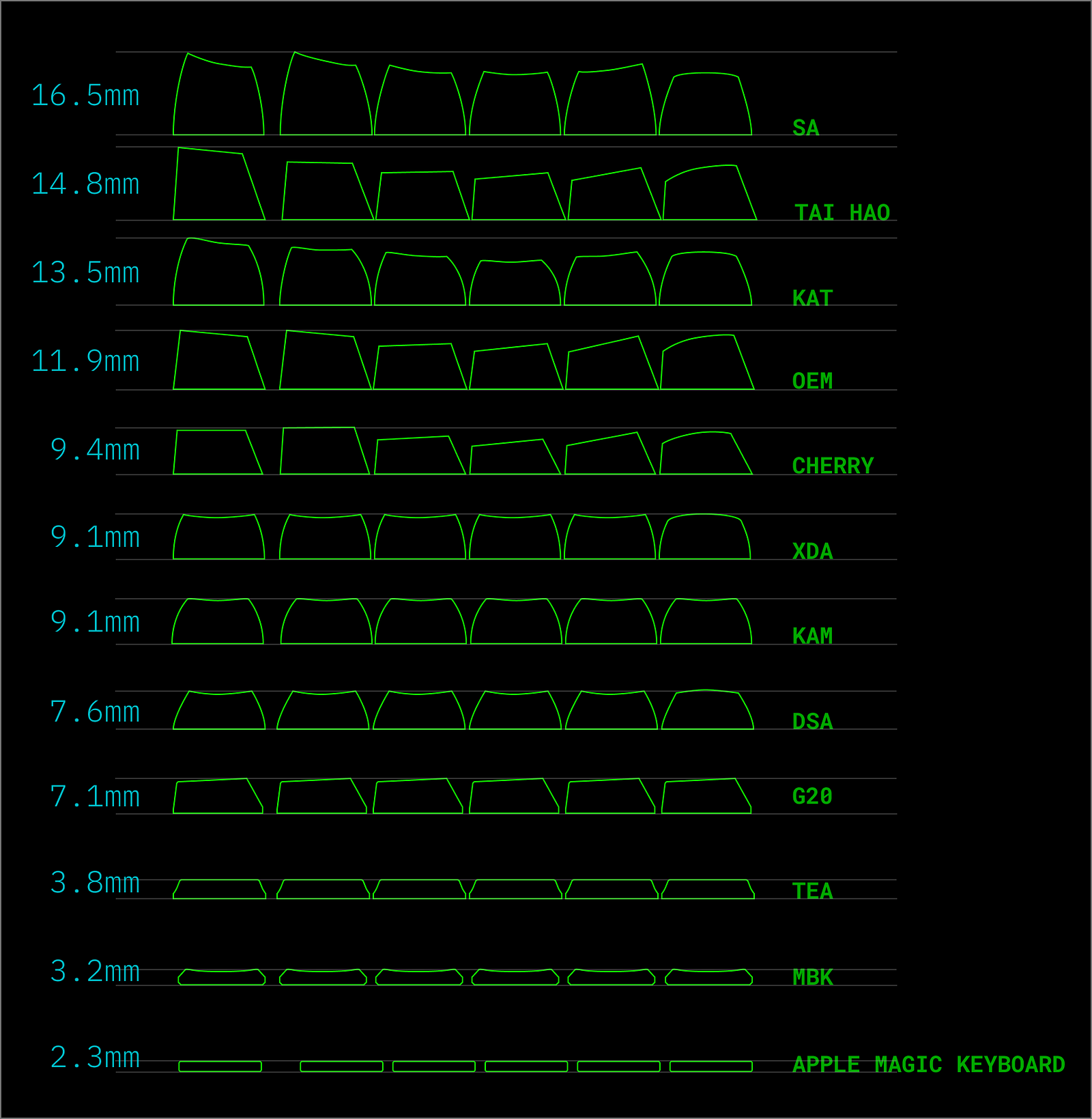
When it comes to Dactyl Manuform, it’s a bit different. Dactyl Manuform is a curved keyboard and its curvature already takes care that your fingers don’t have to travel much when typing. It doesn’t need the additional height or curves that OEM and Cherry profiles provide. Because of that, it’s recommended to use profiles like DSA and XDA with Dactyl Manuforms. DSA and XDA are short uniform profiles. Uniform means that all keycaps are the same. The difference between those two is that XDA is a bit taller. Theoretically, most profiles should fit Dactyl Manuform but I only tested DSA so don’t take my word for it.
Keycaps profiles comparison:
For more info about keycap profiles, you can check out this blog.
Full list of parts
You can find the list with all parts here: https://github.com/DKSadx/dactyl-manuform-blog/tree/main/parts.
I also included screenshots in case the listing is taken down so that you can search the name from the screenshots.
Please read the footnotes in the README.md for detailed explanation.
Total cost
Total cost of all parts that I chose at the time of this writing is: 80.96 USD.
I also checked the prices for all tools mentioned in the Tools section and if you buy all the cheapest tools from AliExpress, it would cost you around 15 USD.
If you’re on a tight budget and theoretically if you buy the cheapest tools, parts and 3D printer filament, it’s possible to build the keyboard for less than 100 USD using only AliExpress.
Tips before you begin building the keyboard
- Keep in mind that it’s really hard to mess something up to the point that it’s not fixable. Most of the work is soldering and if you solder something wrong, you can always desolder it and do it again. Of course, it’s going to take extra time but it’s fixable. Unless you break something or melt the 3D printed case, you should be able to fix almost any mistake you make.
- If you can, use copper tape instead of wires for the rows and columns. You’ll still need wires for some connections but use copper tape for the major part. It’ll save you a lot of time (and I really mean a lot). For the first side, I used normal wires (26 AWG) and it took me the whole day to connect everything and it was really frustrating. The next day, I tried to use the copper tape and realised it’s 4–5 times faster, easier and less stressful. Don’t worry if you haven’t used copper tapes before, this was also my first time. It’s basically a sticky conducting tape. Trust me, it’s worth it.
- It’s good to have spare parts (like additional Pro Micro) in case you break or mess something up. It’s not required but it’s nice to have, for example I was lucky that I didn’t mess something up to the degree that I need a new part but I still had extra.
- Choose a side which will be the main one (one that will have the usb-c plugged into the computer) and build it first. By doing that you will be able to test that side without having to finish the second part.
- Understand the basics of soldering, like how to avoid cold solder.
- If you can, buy Pro Micro that has the pins already soldered in, this will make the build a lot easier because you can use jumper wires to connect the Pro Micro to rows/columns instead of soldering the wires into the Pro Micro’s tiny holes.
- Make sure that you have all the parts so you don’t have to wait a month to finish building the keyboards. For example, I forgot to order USB Type-C 4-Pin Cord Extension Connector and had to wait more than a month to finish the build. Luckily I could use the keyboard without that but it was ugly because I always had a wire hanging from inside the case.
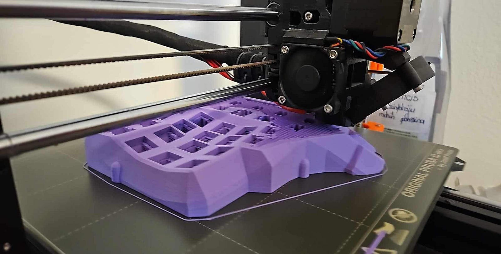
3D printing the case
Disclaimer at the beginning, I didn’t print the case and have 0 experience with 3D printers so I can not tell you about the process. All the 3D printing was done by my friend, the only thing that I did was provide him with the filament and STL files.
If you don’t know anyone with a 3D printer who could help you, there are services online where you upload your STL files and they will print it for you. Not sure about the cost but one of those services is Treatstock.
This is the model I used: Dactyl Manuform GX16. Huge thanks to Scablands for open sourcing the model and providing all the STL files. Also big thanks to/u/oni_strech for providing insights into his build here: Welcome my GX-16 Dactyl Manuform build
My friend’s setup:
3D printer used: Prusa i3 MK3S+
Filament used: PolyTerra™ PLA
Size: 1.75mm
Color: Purple
Weight: 1kg
Price: 20 USD for 1 kg
Url: https://us.polymaker.com/products/polyterra-pla
Time taken to print everything: ~50h (24h per half and around 1–2h for the bottom covers/plates)
The whole build requires less than 400g. If you want to save money, try to find 0.5kg which should be around 10 USD. I didn’t buy the filament on AliExpress because I found a local shop that sells it but there are many filaments on AliExpress if you prefer that option. I also didn’t do any sanding of the case because I liked the look of the 3D printed case.
Making the GX-16 Cable (cable used to connect the two halves)
You will need two cables for the keyboard.
- One that will connect the main keyboard half to the computer. This one will also be used for programming the Pro Micros, in our case this will be the USB Type C cable.
- One that will connect the two halves together, in our case this will be the GX-16 cable.
Keep in mind that you can use any other cable that has at least three wires (cores) in it but you will need to find a different 3D model that supports that cable/connector or modify the above one accordingly.
I chose the GX-16 cable because it was the coolest looking one for me and the 3D model already had support for it.
GX cables also prevent you from shorting your Pro Micros which can happen with TRS/TRRS (reference: Do TRS connectors short adjacent contacts during insertion?)
The GX-16 cable is not that common so there are limited options if you want to buy it. I looked at many and didn’t like any of the options that could ship to my location. Luckily making your own is not that hard and it’s cheap. To make your own GX-16 cable, you will need:
- 2 * male 3 pin GX-16 connector
- 2 * female 3 pin GX-16 connector
- a cable that contains at least 3 wires
3 pins is the minimum amount, if you have a connector with more pins, you can use that one too but only 3 pins will be used/required.
You can find the exact parts including links here
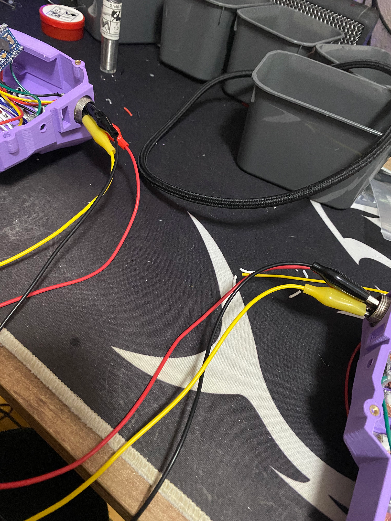
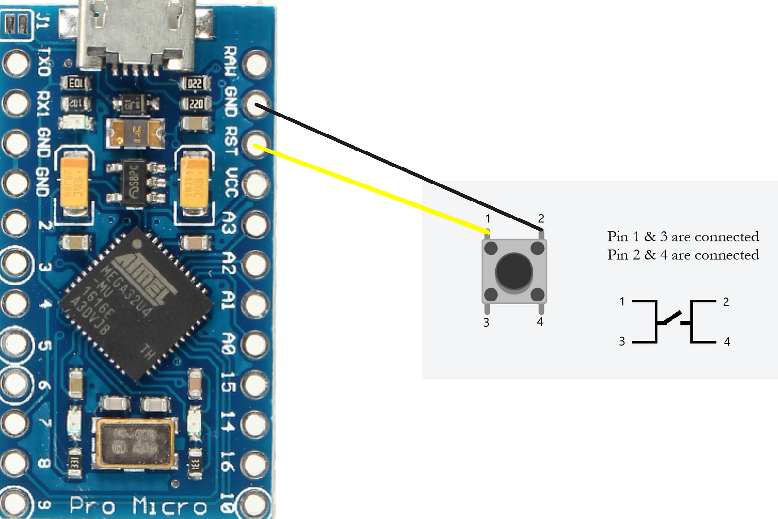
Making the cable is straightforward, there are 3 pins on the connector that need to be soldered to the cable wires. This picture illustrates how the cable should look like. Just instead of alligator clips, we will use the cable.
Steps:
- Place the female ends of the connector in the case holes. It might be tight but it should fit
- Try to connect the male end of the connector to the female end. It should fit without issues
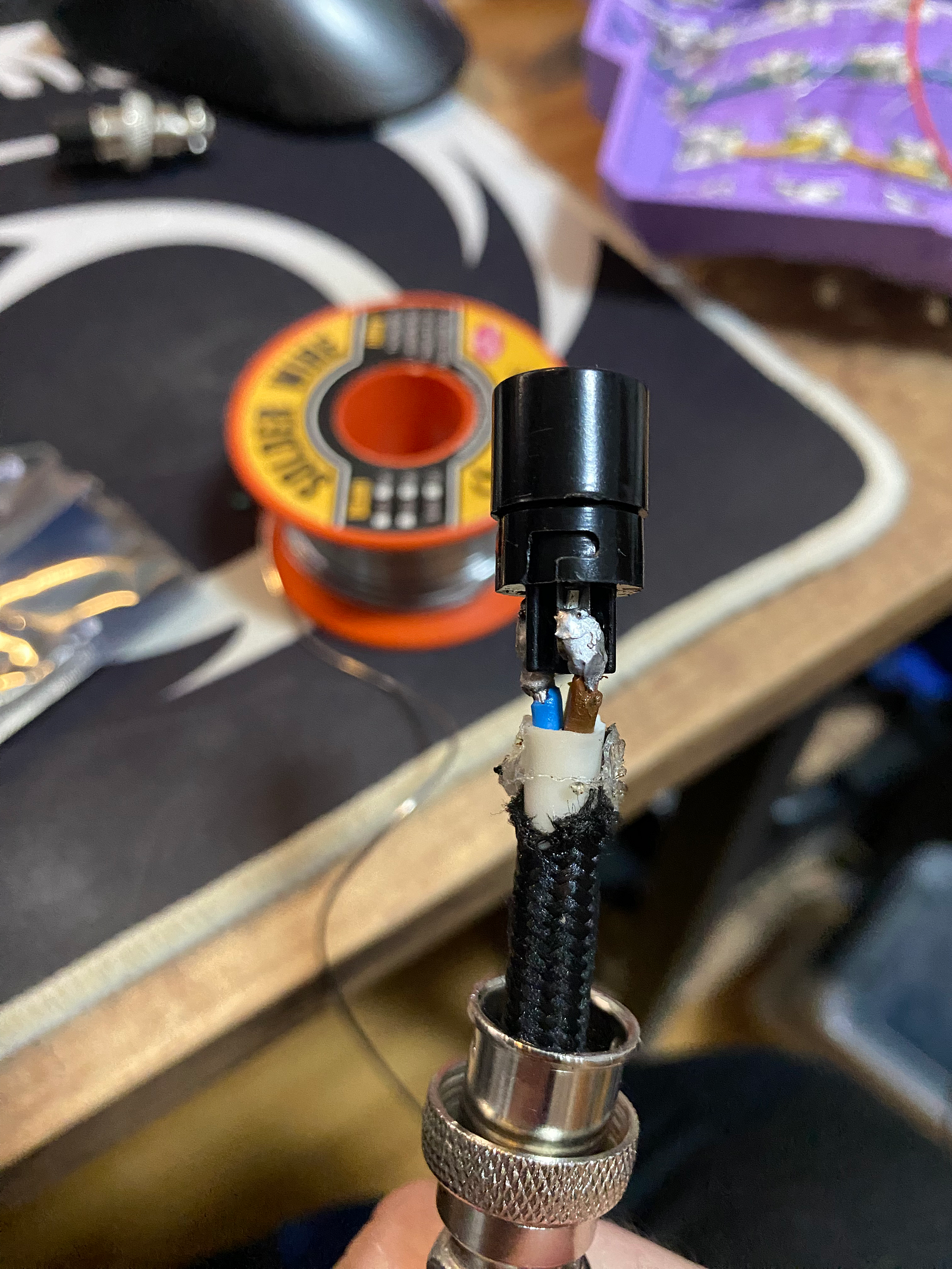
- Solder the wires to the male end of the connector, it should look like the one in the picture below (ignore my ‘amazing’ solder joints, they get the job done 🥲)
- After you’ve finished soldering both ends, the cable should look like this:

- Leave the female connector and the cable for now, we will come back to them later
Making the keyboard
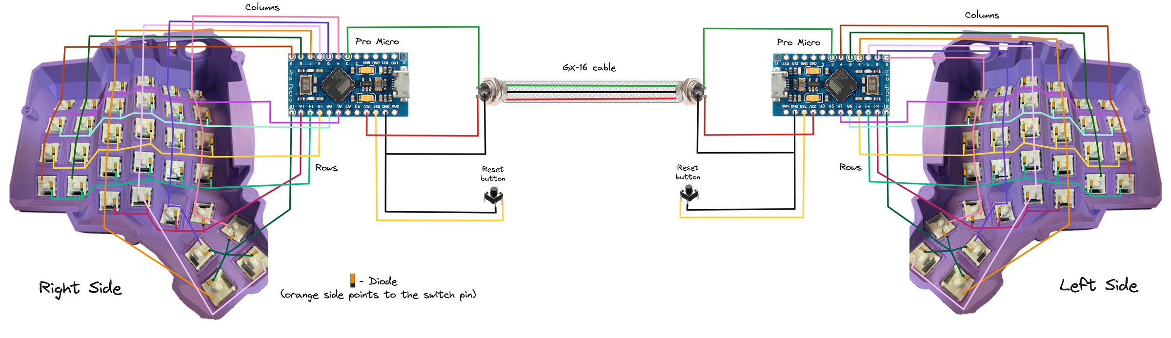
Now with all the parts ready, turn on your soldering iron, set it to 350°C and let’s make the keyboard! We will follow this diagram here:
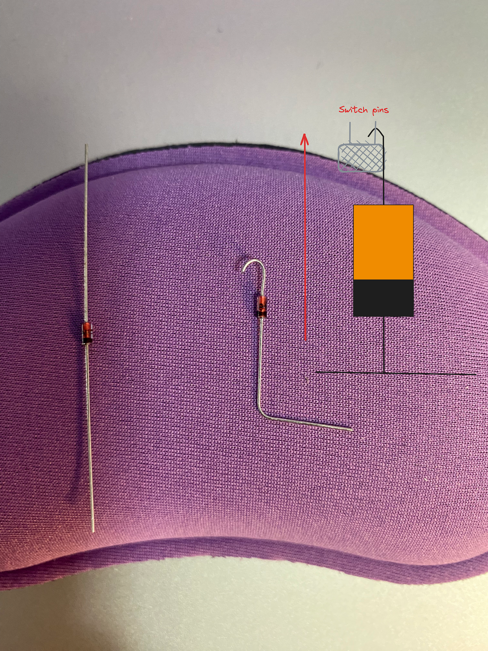
The most important part is the diode orientation! Current can ONLY flow from anode (+) to cathode (-). The point of the diodes is to prevent the current from going in both directions. You don’t need to understand it, just remember that the black line on the diode MUST NOT be next to the pin that comes out of the switch. There is an image on step 4 showing how the diode needs to be oriented.
- Place switches into the holes
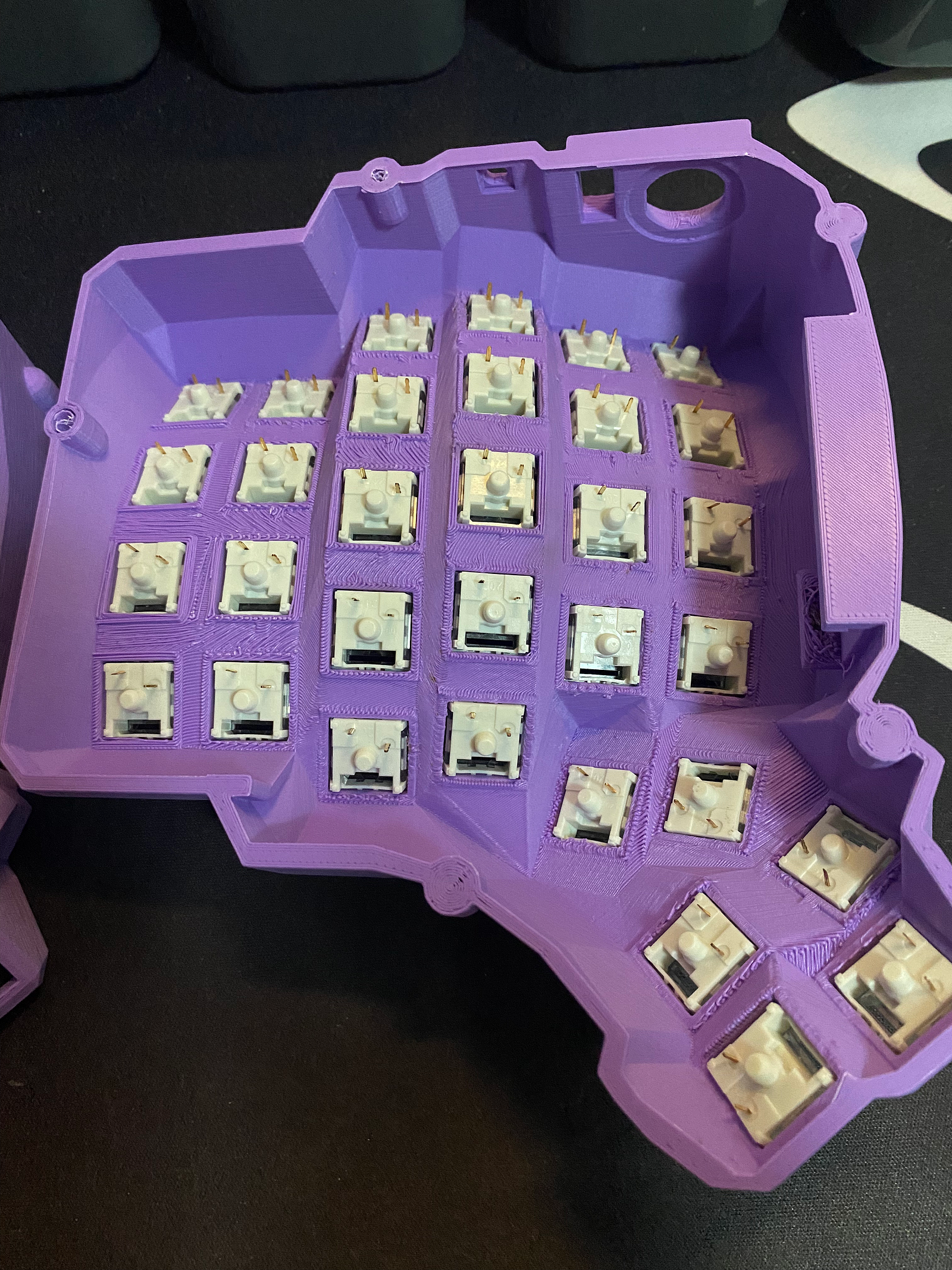
- Connect the columns with the copper tape (or wires) and solder the switch pins to the copper tape
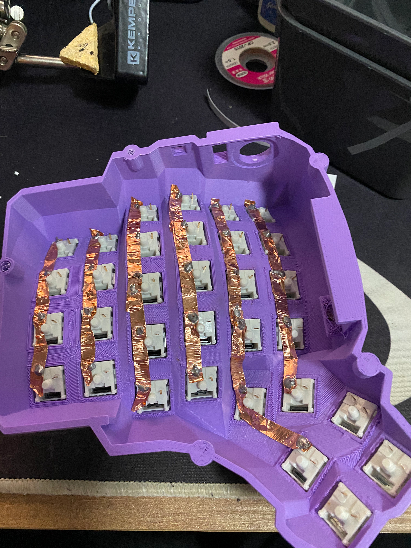
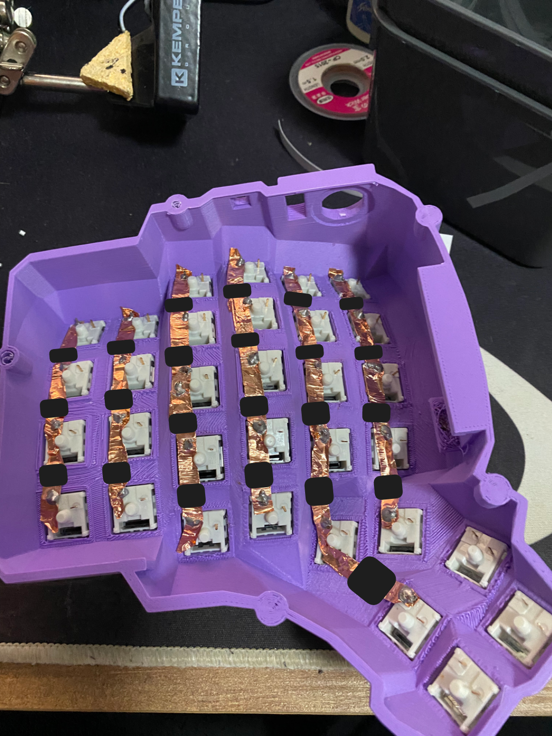
- Place insulating (non-conducting) tape on the places where rows and columns cross. Feel free to do it however you want, the only important part is that the wires don’t touch
- We need to prepare the diodes that will be used for the rows. Use tweezers and wire cutters to make small hooks so that’s easier to solder them to the switches later. Make sure that the diode orientation is correct!
- Connect the rows using diodes, most diodes have long enough wires on them so you can use those wires to create rows (connections). It should look something like this:
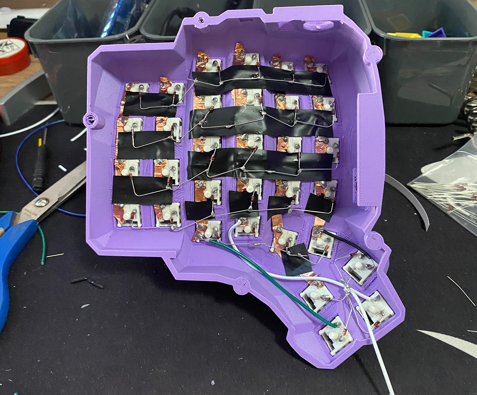
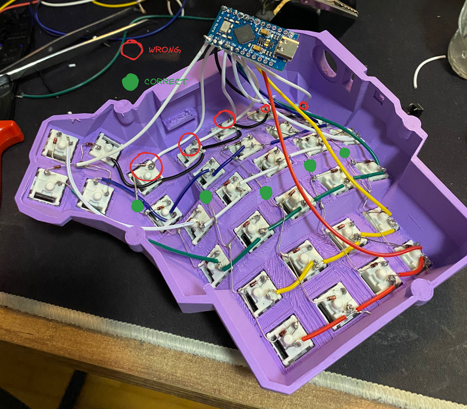
- Solder a normal wire to the end of each row and column. Those wires will go into the Pro Micro later. It’s not important where exactly you connect the wire to the column/row. You can choose any place you want because the whole row/column acts as a single wire.
Just don’t connect it to the side where the anode is (side next to the switch pin). I made that mistake and it took me some time to realise what was the issue. (I made the mistake on my left half, that’s the reason why there are wires instead of copper tape on the below image)
-
Follow the main diagram and connect the rows and columns to the corresponding pins on the Pro Micro. This can be very easy or quite challenging depending on the Pro Micro you’ve got. If your Pro Micro has the pins already soldered in, you can use jumper wires and make your life 5 times easier but if your Pro Micro doesn’t come with the pins already soldered (as mine didn’t), you will have two options:
- Solder the pins and use the jumper wires to connect the rows and columns to Pro Micro (recommended)
- Solder the wires directly into the holes (I did this, it’s not fun).
Both options can be difficult for a novice solderer because the distance between the holes is really small and you must be really careful when soldering so that there is no connection between the holes. Double check every hole because if there’s even a tiny bit of solder that touches two holes, the keyboard won’t work as expected. If you have a multimeter, you can use it to check the connections.
-
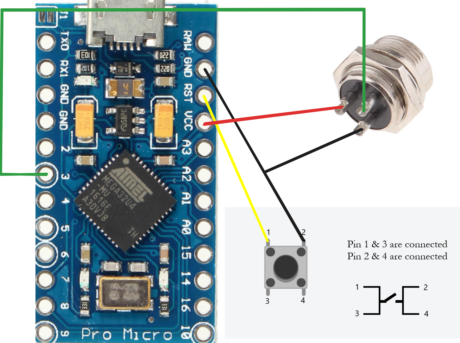
Connect the reset button as shown in the image below. We will use the same ground (GRD) pin for both the reset button and the GX-16 cable.
- Place the GX-16 female connector in the corresponding hole on the case. It’s up to you which GX-16 pin you connect to which Pro Micro pin but you must do the same for both connectors on both sides. After you solder the wires to the GX-16 connector, place it in the corresponding hole and try to attach the GX-16 cable to both female connectors. You only need to check if the connections are correct, you don’t need to solder the other female connector to the other Pro Micro for now.
Just keep in mind that the GX-16 cable must connect VCC from one Pro Micro to the VCC of the other Pro Micro, same goes for GND and PIN 3.
VCC → VCC
GND → GND
PIN 3 → PIN 3
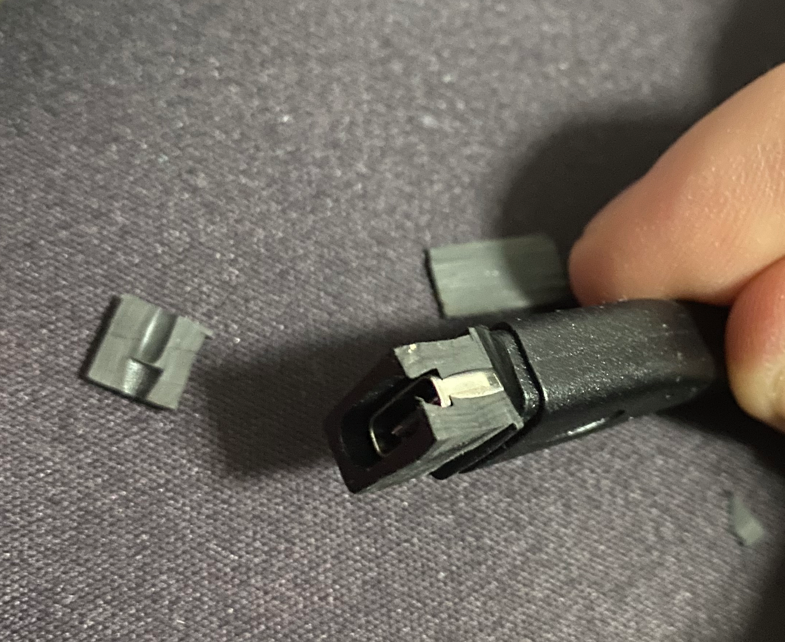
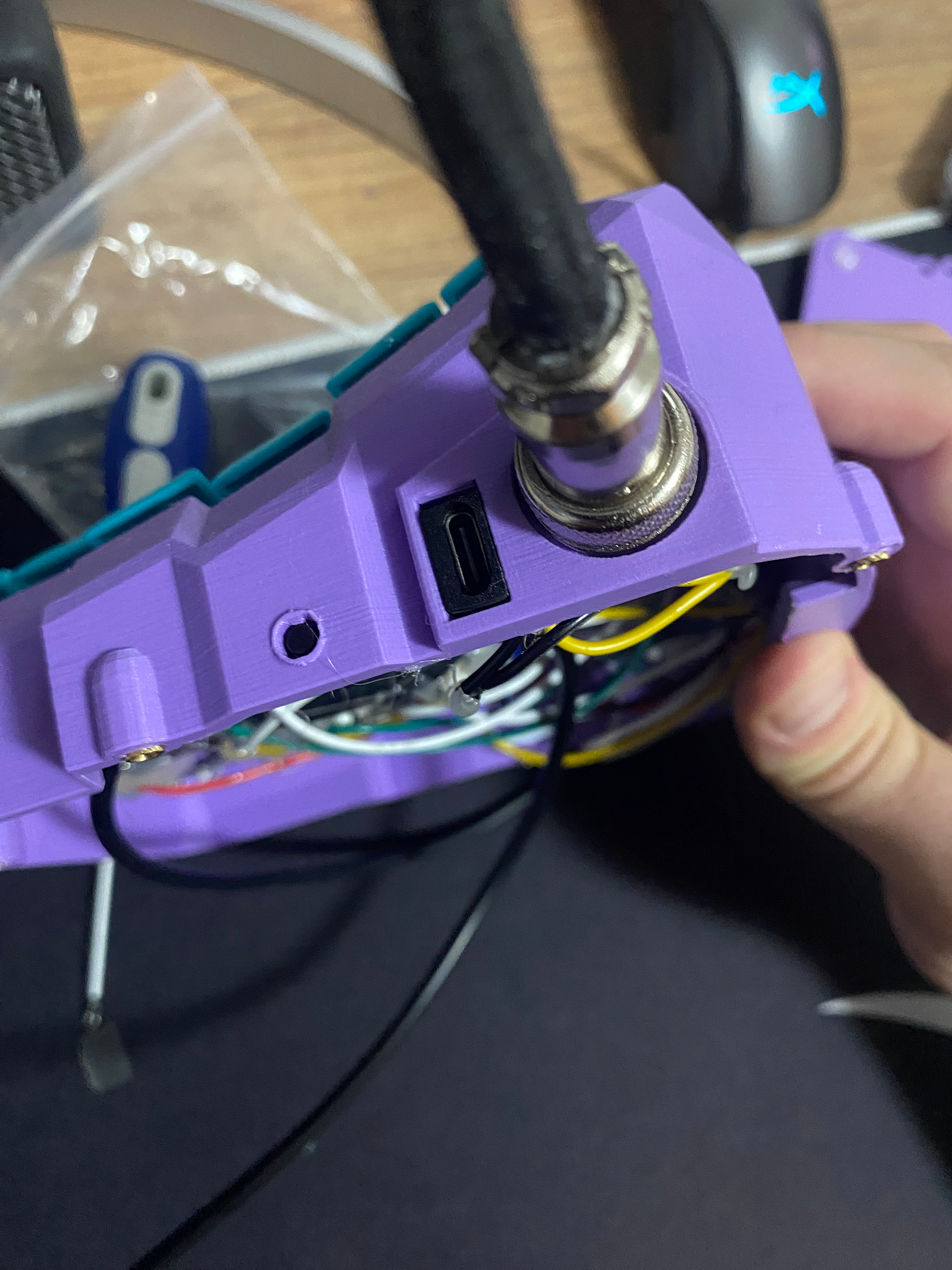
- If you ordered the USB-C extension cable from the table above, you will see that it’s too large for the hole on the case. To fix that, we will need to remove some of the rubber from it. You can use something sharp like a knife or scissors to remove the rubber. Cut it just enough so that you can push it into the hole. (I’m sure you can do a better job than I did 🥲)
After you’re done with cutting, solder the wires together (green to green, red to red, white to white) and insert the cable into the Pro Micro. Put some insulation tape or hot glue over the joints just to be safe.
- (optional but recommended) Now you are able to test if the keyboard half is working correctly.
If you want to test it, go to Programming the keyboard section and once you make sure that the half is working correctly, continue with the steps.
You can test if the keys are working correctly on https://keyboardchecker.com/.
-
Do steps 1–12 for the other half too
-
After you have finished both halves, try connecting them with the GX-16 cable. If you followed all the above steps and did everything in the Programming the keyboard section, the keyboard should work. If it’s not working correctly, go to the section Troubleshooting issues and try the fixes mentioned there.
-
After you thoroughly tested the keyboard and all keys are working as expected, you can now hot glue the reset buttons, usb-c extension cables and GX-16 female connectors to the case
-
(optional but recommended) You can also hot glue the switches to the case. There are pros and cons for this.
Pros:
- Switches are not fixed to the case which means that they can fall off and you risk that the wires might snap. Hot gluing will prevent this
- If you want to change the keycaps, it will be easier
- Even if the solder joint is not perfect, hot glue should keep it in place
Cons:
- Hot gluing will make it a lot harder to fix any mistakes that you made during the build
- When a switch dies (which can happen especially with cheap switches), it will be a lot harder to replace because you will have to remove the hot glue first
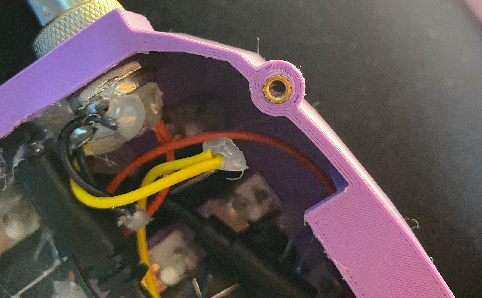
- The last thing we need to do is fix the insert nuts to the case.
If you try to put the insert nuts into the holes, you'll see that the holes are too wide for M3 nuts. I also tried M4 ones, but those were too big.
I'm not sure if this is intentional in the 3D print model, but the only approach that worked for me was to screw a bolt into the nut, put some hot glue in the hole, and then press the nut (with the bolt inside) into the hole. Wait for the hot glue to cool, then unscrew the bolt. If there's any excess hot glue, remove it with a knife or scalpel.
It should look like this:
 Screw the lid onto the case but not too tight because the nuts can come off if they’re screwed on too tight.
- Put the keycaps on and enjoy 🥳
Programming the keyboard
Congratulations! 🎉 If you came to this section, you’ve most likely finished one or both halves of the keyboard. Good job, you’ve almost made it to the end!
If the guides on the internet are to be believed, programming Dactyl Manuform will be easy for most people, but for me the happy path didn’t happen. I had to spend a few hours troubleshooting what went wrong, and having 0 experience with programming keyboards and QMK didn’t help. In case the happy path didn’t happen to you as well, I hope my experience will be helpful. I didn’t go too deep into how QMK works, I just wanted to know enough so that I can program my keyboard.
I will provide the standard steps first and if it works for you, enjoy your new keyboard 🥳 but if not, try the solutions from the Troubleshooting issues section. Don’t get confused, the same code is used for both Pro Micros. There is logic that will handle what the leader half does and what the follower half does. Steps:
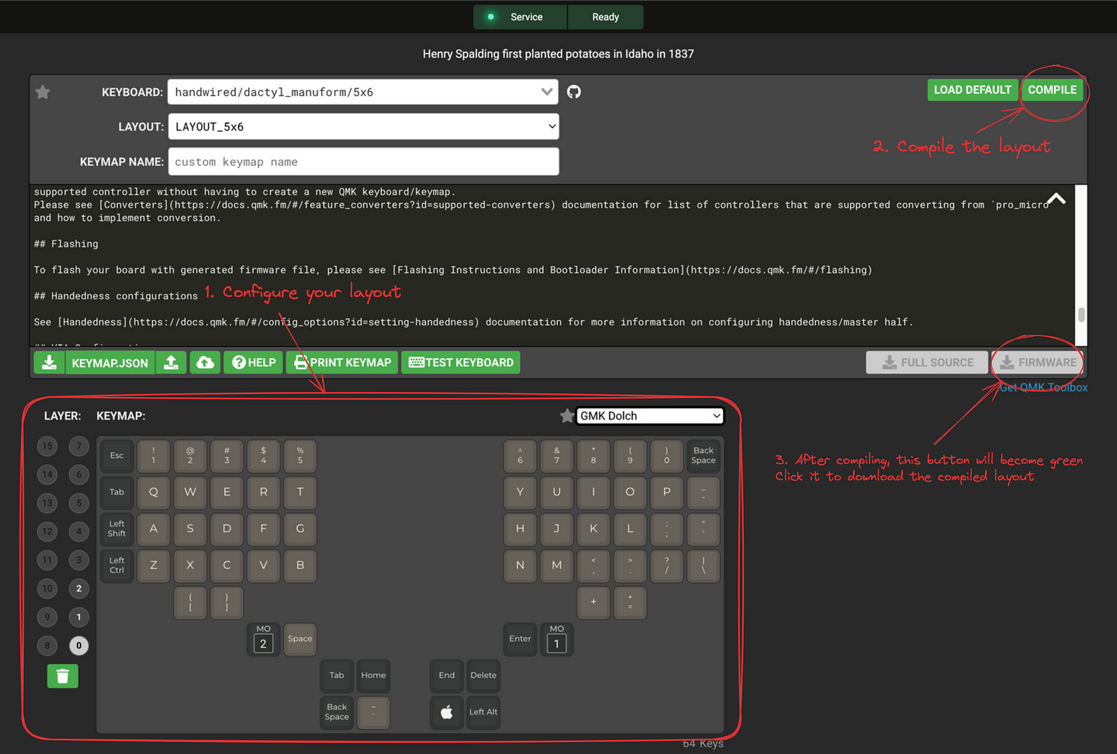
- Go to QMK Configurator (https://config.qmk.fm/#/handwired/dactyl_manuform/5x6/LAYOUT_5x6) and configure your desired layout.
You can check out my layout in the section My layout, feel free to use it if you want. If you are new to QMK, research a bit about layers and mod keys
-
When you finish configuring the layout, click COMPILE
-
Click on FIRMWARE and it should start downloading the compiled
.hexfile
-
Download QMK Toolbox (https://github.com/qmk/qmk_toolbox)
-
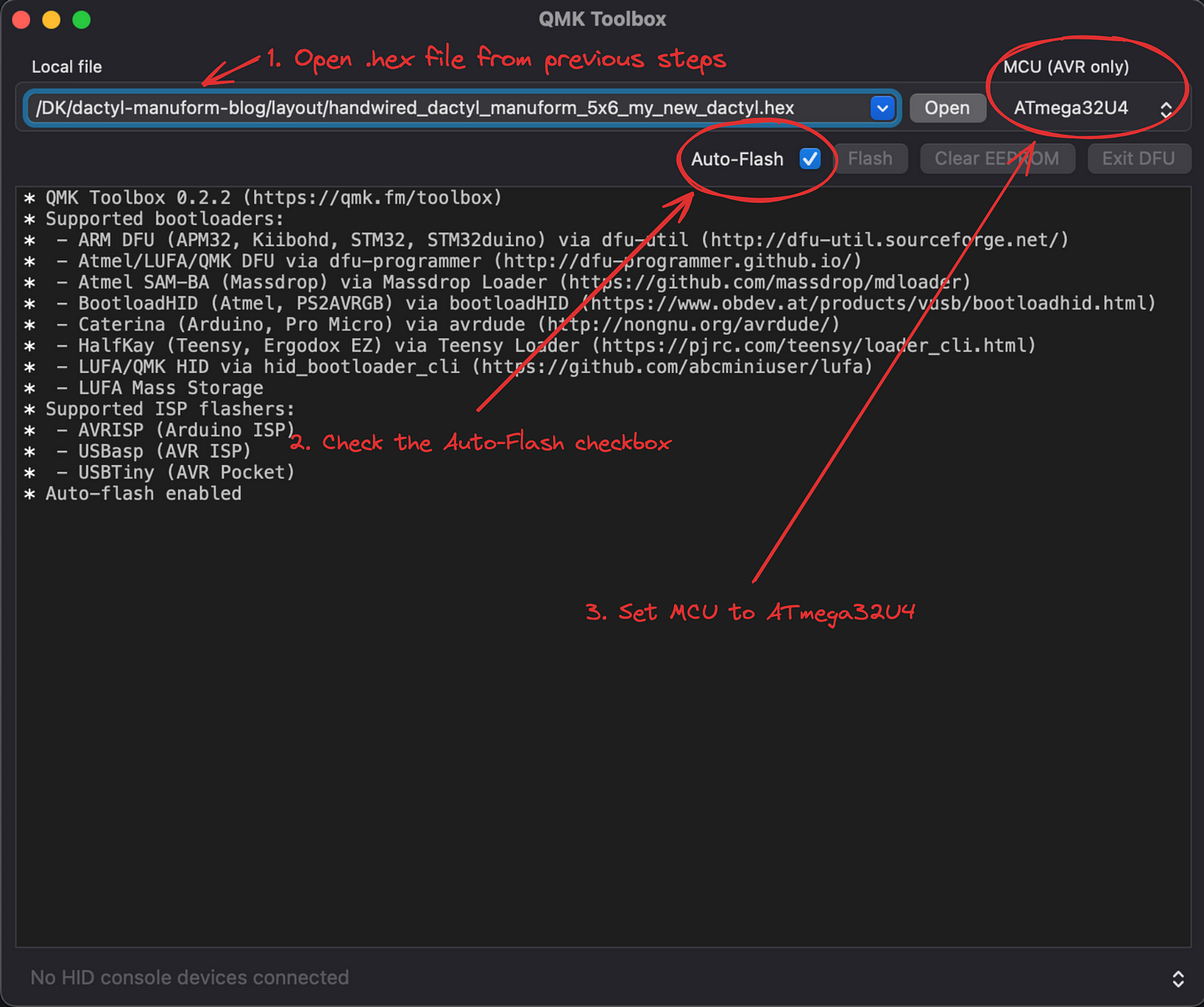
Open QML Toolbox and open the
.hexfile that you downloaded in step 3 -
Check the
Auto-Flashcheckbox -
Set MCU (AVR Only) to
ATmega32U4
-
Connect one half of the keyboard via the usb cable to your computer
-
Hold the reset button for 2–3 seconds and let go, QMK toolbox will start flashing the software
-
Go to https://keyboardchecker.com/ and test your half (don’t worry if it’s reversed, we will fix that later)
-
Disconnect the cable and connect it to the other Pro Micro. Do the steps 9 and 10 for the other half too
-
Connect both halves via the GX-16 cable and test if it works
-
If the halves are reversed, disconnect the usb cable from the Pro Micro and insert it into the other one and try again
-
If everything works, 🎉 Congratulations, you’ve done it! You are ready to use the keyboard! But if it doesn’t work go to Troubleshooting issues section and try the solutions mentioned there.
Troubleshooting issues
1. Both halves are working when you connect them separately but they are not working together
This can happen because of both hardware and software reasons:
- The GX-16 male side is not correctly soldered to the cable (wires).
- The GX-16 female side is not correctly connected to the Pro Micro
- The Pro Micros can’t determine which Pro Micro is the leader. (I had this issue)
To fix 1 and 2, take a good look at the diagram and make sure that GX-16 cable is soldered and connected correctly.
To fix 3, you will need to make a change in the code. Fixing this is a bit more complicated, there aren’t many resources regarding this issue so it wasn’t that easy to figure out. The main issue is that the Pro Micros can not determine which one is the leader, so we have to configure that manually in the code. We will need to edit the source code so we can not use the .hex file which means that we can not use the COMPILE option in the QMK Configurator. We have to do it manually.
-
Instead of downloading the
.hexfile, download theKEYMAP.JSONfile from the QMK Configurator. Pro Micro can't read JSON so we have to convert it to C. We will need to use the terminal to do this but it won't be too complicated -
Clone the main QMK firmware GitHub repo
git clone https://github.com/qmk/qmk_firmware.git -
Set up the project
cd qmk_firmware make git-submodule cd keyboards/handwired/dactyl_manuform/5x6/keymaps -
We will use the default layout as a template for our new one
# I chose my_new_dactyl as an example, you can choose any name you want cp -r default my_new_dactyl -
Now we need to add the most important line. This line instructs the Pro Micro to be the leader half if there is a USB connection, otherwise it will be a follower.
Openconfig.hin any text editor and add this line anywhere in the file#define SPLIT_USB_DETECT -
Download your configured layout as json from https://config.qmk.fm/#/handwired/dactyl_manuform/5x6/LAYOUT_5x6 to this location:
qmk_firmware/keyboards/handwired/dactyl_manuform/5x6/keymaps/my_new_dactyl -
Convert the JSON layout to C code
# handwired_dactyl_manuform_5x6_layout_5x6_mine.json is the file you downloaded from previous step. It may be different in your case qmk json2c handwired_dactyl_manuform_5x6_layout_5x6_mine.json -o keymap.c -
Compile your layout
qmk compile -kb handwired/dactyl_manuform/5x6 -km my_new_dactyl -
After you compiled your layout, there will be a new file called
handwired_dactyl_manuform_5x6_my_new_dactyl.hexin the root ofqmk_firmwaredirectory. Go to QMK Toolbox, open the new.hexfile and try to flash the keyboard again (connect and hold reset). TADA 🎉 it should work now. If not, it's probably a hardware issue.
2. One key acts as two aka produces more than one character
When this happens, it’s because somewhere the wires of rows and/or columns are touching. To fix this, inspect all the columns/rows where this is happening and remove the wrong connections.
3. One key is not working
This can happen because of a few reasons:
- The diode orientation is wrong
- It’s not soldered correctly to the switch, the current is not reaching the switch
- The switch is not working, it’s broken/dead
4. More keys are not working
- If the whole row is not working, it could be because you soldered the connection on the wrong side of the diode. Go to section Making the keyboard and look at the picture of the mistake I made during my build
- Row/column is not correctly soldered to the pin on Pro Micro
- Pin on Pro Micro is broken/dead (very unlikely)
5. Pro Micro won’t flash even though its light is on when connected to the pc
- Check if you used GND and RST pins
- Check if you used the correct pins on the reset button, look at the below gif
6. Pro Micro light won’t turn on when connected to pc
- Pro Micro doesn’t work, it’s broken
- USB cable doesn’t work
7. Pro Micro automatically resets when plugged into the pc
- GND and RST are shorted somewhere, check if there is solder between those pins
- You used the wrong pins on the reset button, look at the picture in issue 5
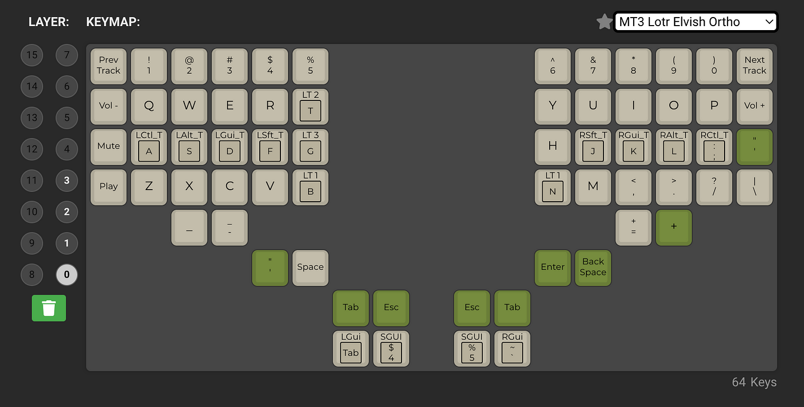
My layout
This is my current layout but I’m changing it constantly. If you want to try it out, you can find all the files here: https://github.com/DKSadx/dactyl-manuform-blog/tree/main/layout.
If you’re wondering why I stuck with QWERTY instead of DVORAK or COLEMAK, there is no specific reason, I just wanted to get familiar with touch typing and split keyboards first. I will probably try those layouts sometime in the future.
Layer 0:
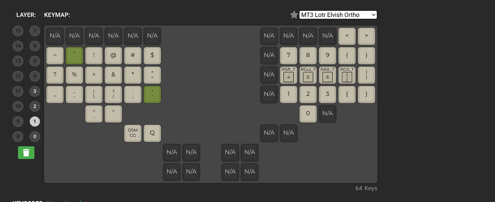
Layer 1:
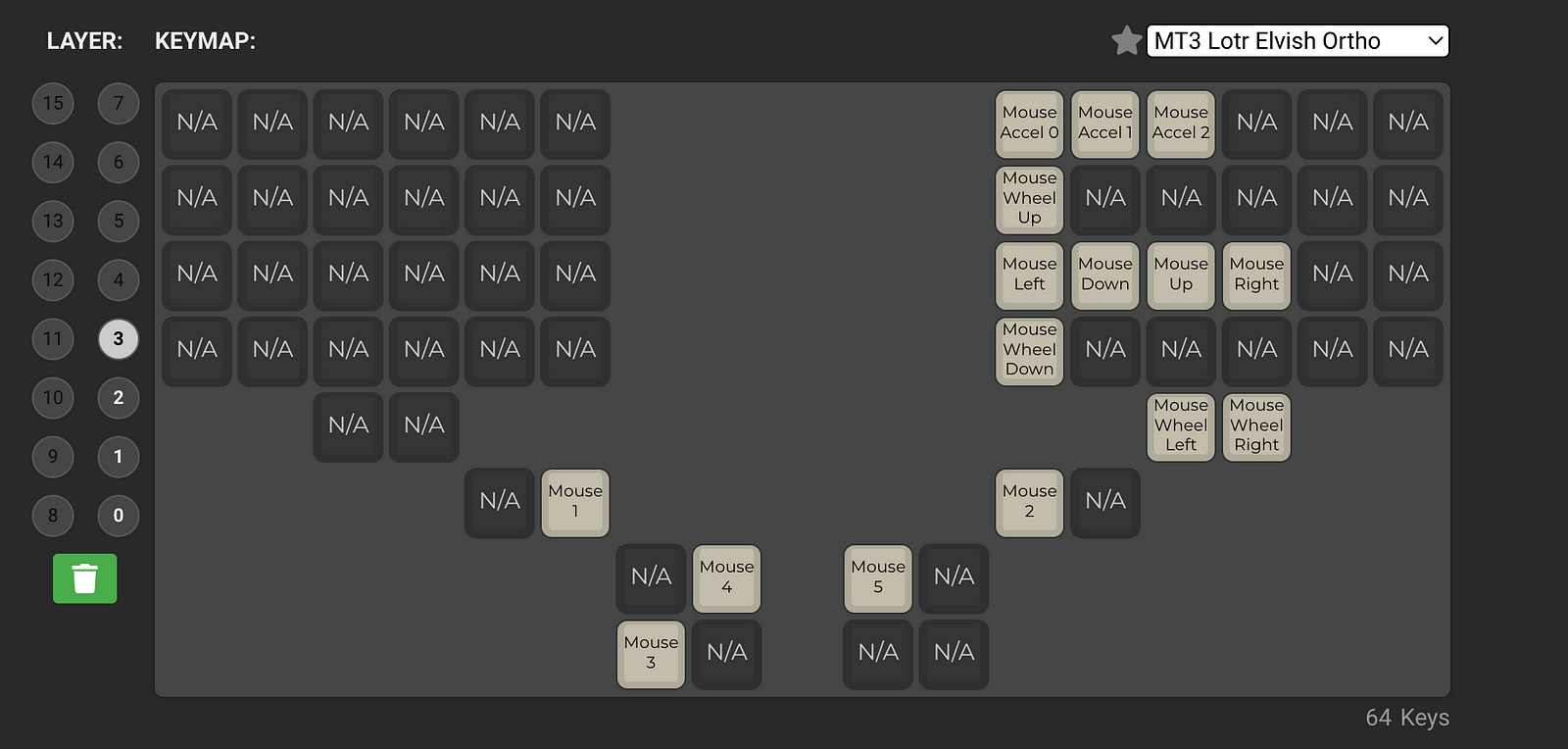
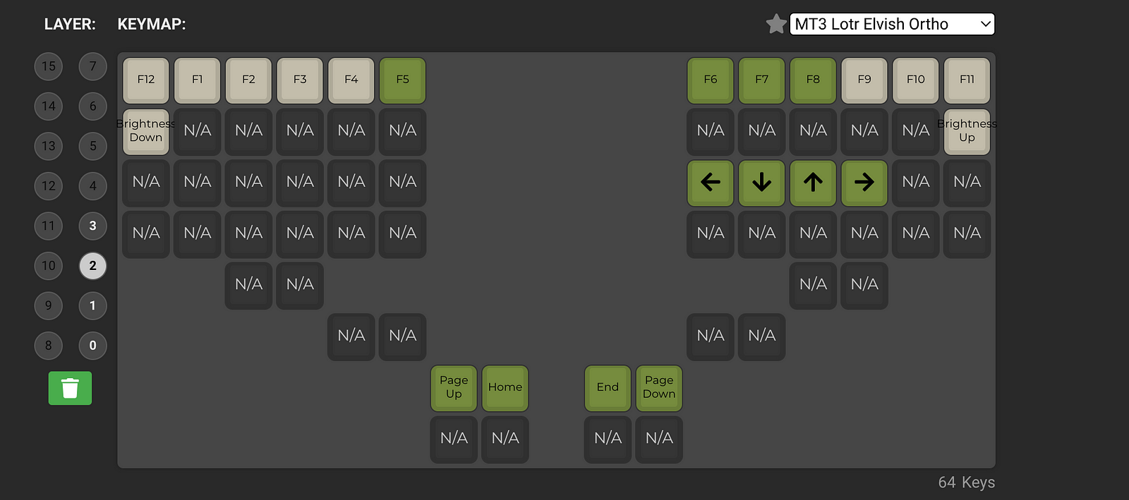
Layer 2:
Layer 3 (mouse):